Saturday, November 5, 2016

Switching Architectures - Network Traffic Models

Network Traffic Models

Traffic flow is an important consideration when designing scalable, efficient
networks. Fundamentally, this involves understanding two things:
• Where do resources reside?
• Where do the users reside that access those resources?

Legacy networks adhered to the 80/20 design, which dictated that:
• 80 percent of traffic should remain on the local network.
• 20 percent of traffic should be routed to a remote network.

To accommodate this design practice, resources were placed as close as
possible to the users that required them. This allowed the majority of traffic
to be switched, instead of routed, which reduced latency in legacy networks.

The 80/20 design allowed VLANs to be trunked across the entire campus
network, a concept known as end-to-end VLANs:


End-to-end VLANs allow a host to exist anywhere on the campus network,
while maintaining Layer-2 connectivity to its resources.

However, this flat design poses numerous challenges for scalability and
performance:
• STP domains are very large, which may result in instability or
convergence issues.
• Broadcasts proliferate throughout the entire campus network.
• Maintaining end-to-end VLANs adds administrative overhead.
• Troubleshooting issues can be difficult.

As network technology improved, centralization of resources became the
dominant trend. Modern networks adhere to the 20/80 design:
• 20 percent of traffic should remain on the local network.
• 80 percent of traffic should be routed to a remote network.

Instead of placing workgroup resources in every local network, most
organizations centralize resources into a datacenter environment. Layer-3
switching allows users to access these resources with minimal latency.

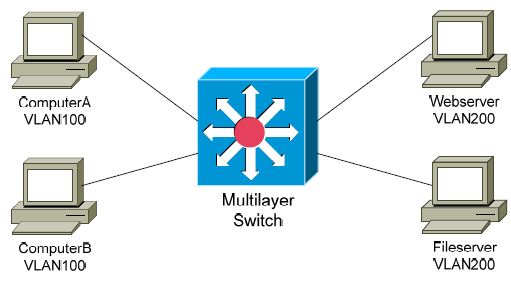
The 20/80 design encourages a local VLAN approach. VLANs should stay
localized to a single switch or switch block:


This design provides several benefits:
• STP domains are limited, reducing the risk of convergence issues.
• Broadcast traffic is isolated within smaller broadcast domains.
• Simpler, hierarchical design improves scalability and performance.
• Troubleshooting issues is typically easier.

There are nearly no drawbacks to this design, outside of a legacy application
requiring Layer-2 connectivity between users and resources. In that scenario,
it’s time to invest in a better application.


The Cisco Hierarchical Network Model

Switching Architectures Hierarchical Model – Practical Application

Cisco Hierarchical Model – Practical Application


The above example illustrates common block types:
• User block – containing end users
• Server block – containing the resources accessed by users
• Edge block – containing the routers and firewalls that connect users
to the WAN or Internet
Each block connects to each other through the core layer, which is often
referred to as the core block. Connections from one layer to another should
always be redundant.

A large campus environment may contain multiple user, server, or edge
blocks. Limiting bottlenecks and broadcasts are key considerations when
determining the size of a block.

Switching Architectures Hierarchical Model – Core Layer

Hierarchical Model – Core Layer


The core layer is responsible for connecting all distribution layer switches.

The core is often referred to as the network backbone, as it forwards traffic
from to every end of the network.

Switches at the core layer typically have the following characteristics:
• High-throughput Layer-3 or multilayer forwarding
• Absence of traffic filtering, to limit latency
• Scalable, redundant links to the distribution layer and other core
switches
• Advanced QoS functions

Proper core layer design is focused on speed and efficiency. In a 20/80
design, most traffic will traverse the core layer. Thus, core switches are often
the highest-capacity switches in the campus environment.

Smaller campus environments may not require a clearly defined core layer
separated from the distribution layer. Often, the functions of the core and
distribution layers are combined into a single layer. This is referred to as a
collapsed core design.

(Reference: CCNP Switch 642-813 Official Certification Guide by David Hucaby. Cisco Press)


Switching Architectures Hierarchical Model – Distribution Layer


Hierarchical Model – Distribution Layer


The distribution layer is responsible for aggregating access layer switches,
and connecting the access layer to the core layer. Switches at the distribution
layer typically have the following characteristics:
• Layer-3 or multilayer forwarding
• Traffic filtering and QoS
• Scalable, redundant links to the core and access layers

Historically, the distribution layer was the Layer-3 boundary in a
hierarchical network design:
• The connection between access and distribution layers was Layer-2.
• The distribution switches are configured with VLAN SVIs.
• Hosts in the access layer use the SVIs as their default gateway.

This remains a common design today.
However, pushing Layer-3 to the access-layer has become increasingly
prevalent. VLAN SVIs are configured on the access layer switch, which
hosts will use as their default gateway.

A routed connection is then used between access and distribution layers,
further minimizing STP convergence issues and limiting broadcast traffic.

(Reference: CCNP Switch 642-813 Official Certification Guide by David Hucaby. Cisco Press)

Switching Architectures Hierarchical Model – Access Layer

Hierarchical Model – Access Layer


The access layer is where users and hosts connect into the network.

Switches at the access layer typically have the following characteristics:
• High port density
• Low cost per port
• Scalable, redundant uplinks to higher layers
• Host-level functions such as VLANs, traffic filtering, and QoS
In an 80/20 design, resources are placed as close as possible to the users that
require them. Thus, most traffic will never need to leave the access layer.

In a 20/80 design, traffic must be forwarded through higher layers to reach
centralized resources.

(Reference: CCNP Switch 642-813 Official Certification Guide by David Hucaby. Cisco Press)

Cisco Switch ADSL Port Configuration Best Practice - straight forward and Easy

 ADSL Port Configuration  only change  yellow shaded text

interface GigabitEthernet0/2
 description "CONNECTED TO INT"
 no ip address
 duplex auto
 speed auto
 pppoe enable group global
 pppoe-client dial-pool-number 1
!

interface GigabitEthernet0/1

 ip nat inside

 no cdp enable

interface Dialer1
 bandwidth 100000
 ip address negotiated
 no ip redirects
 no ip unreachables
 no ip proxy-arp
 ip mtu 1492
 ip nat outside
 ip virtual-reassembly in
 encapsulation ppp
 ip tcp adjust-mss 1452
 dialer pool 1
 dialer idle-timeout 0
 dialer persistent
 ppp pap sent-username EnterISPUserName password EnterISPPassword
        
 no cdp enable
ip nat translation timeout 20
ip nat translation max-entries all-vrf 200000000
ip nat inside source list nat interface Dialer1 overload
ip access-list extended nat
 permit ip any any
ip route 0.0.0.0 0.0.0.0 Dialer1

Cisco Switch Configuration Best Practice - straightforward and Easy

Advanced straight  Layer 3 switch configuration only replace the highlighted Words  


no ip routing
no service pad
service tcp-keepalives-in
service tcp-keepalives-out
service timestamps debug datetime localtime show-timezone
service timestamps log datetime localtime show-timezone
service password-encryption
service internal
service pt-vty-logging
service sequence-numbers
service counters max age 10
!
hostname EnterSwitchName
!
enable secret EnterPassword
!
username EnetrUserName pri 15 sec EnterPassword
!
!
no service pad
no ip finger
no service finger
no ip source-route
no service tcp-small-servers
no service udp-small-servers
no service config
no file verify auto
no ip source-route
no ip http server
no ip gratuitous-arps
ip subnet-zero
!
clock timezone EnterTimeZoneForExamplecUAE 4
vtp domain EnterDomainName
vtp mode transparent
udld aggressive
udld message time 30
ip subnet-zero
no ip source-route
no ip gratuitous-arps
no ip domain-lookup
ip domain-name EnterDomainName
!
!
!
!
!
!
no errdisable detect cause dhcp-rate-limit
errdisable recovery cause udld
errdisable recovery cause bpduguard
errdisable recovery cause security-violation
errdisable recovery cause channel-misconfig
errdisable recovery cause pagp-flap
errdisable recovery cause dtp-flap
errdisable recovery cause link-flap
errdisable recovery cause gbic-invalid
errdisable recovery cause l2ptguard
errdisable recovery cause psecure-violation
errdisable recovery cause dhcp-rate-limit
errdisable recovery cause vmps
errdisable recovery cause storm-control
errdisable recovery interval 60
!
!
!
spanning-tree mode rapid-pvst
spanning-tree loopguard default
spanning-tree portfast bpduguard default
spanning-tree portfast bpdufilter default
!

!
vlan 10
 name EnterVlanNameForExample ENDUSER_VLAN
!
vlan 17
 name EnterVlanNameForExample WIRELESS_VLAN
!
vlan 18
 name EnterVlanNameForExample ACESSPOINT_VLAN
!
!
!
interface range GigabitEthernet0/1 - 47
description EnterDescriptionForExample CONNECTED TO END USERS
 switchport access vlan 10
 switchport mode access
 spanning-tree portfast
 spanning-tree bpduguard enable
!
interface GigabitEthernet0/48
 description "ACCESS POINT"
 switchport trunk encapsulation dot1q
 switchport trunk native vlan 18
 switchport trunk allowed vlan 17,18
 switchport mode trunk
 spanning-tree bpduguard disable
!
interface range GigabitEthernet1/1
 description "CONNECTED TO CORE SW"
 switchport trunk encapsulation dot1q
 switchport mode trunk
 switchport nonegotiate
 switchport trunk allowed vlan AddAllVlansForExample  17-18,10
 logging event trunk-status
 storm-control broadcast level 70.00
!
interface GigabitEthernet1/2
description From <NOT IN USE>
shutdown
!
interface GigabitEthernet 1/3
description From <NOT IN USE>
shutdown
!
interface GigabitEthernet 1/4
description From <NOT IN USE>
shutdown
!
!
interface Vlan10
 description EnterDescriptionForExample block A switch
 ip address 192.168.10.2 255.255.255.0
no shut
!
ip default-gateway 192.168.10.1
!
no ip http server
no ip http secure-server
!
access-list 11 per 192.168.30.30
ntp access-group peer 11
ntp server 192.168.30.30
ip domain name EnterDomainName
crypto key generate
1024
ip ssh ver 2
no ip domain name EnterDomainName
!
!
privilege exec level 1 show
banner motd ^
       *************************************
       *  Unauthorized access prohibited   *
       *      ONLY ITD NETWORK STAFF       *
       *************************************
^

!
line con 0
 exec-timeout 5 0
 password EnterPassword
  logging synchronous
line vty 0 4
 exec-timeout 5 0
 login local
 line vty 5 15
 exec-timeout 5 0
 login local
 !

Thursday, November 3, 2016

What is a VLAN, And Layer Function

VLANs – A Layer-2 or Layer-3 Function?


By default, a switch will forward both broadcasts and multicasts out every
port but the originating port.

However, a switch can be logically segmented into multiple broadcast
domains, using Virtual LANs (or VLANs). VLANs are covered in
extensive detail in another guide.

Each VLAN represents a unique broadcast domain:
• Traffic between devices within the same VLAN is switched
(forwarded at Layer-2).
• Traffic between devices in different VLANs requires a Layer-3
device to communicate.

Broadcasts from one VLAN will not be forwarded to another VLAN. The
logical separation provided by VLANs is not a Layer-3 function. VLAN
tags are inserted into the Layer-2 header.

Thus, a switch that supports VLANs is not necessarily a Layer-3 switch.
However, a purely Layer-2 switch cannot route between VLANs.

Remember, though VLANs provide separation for Layer-3 broadcast
domains, they are still a Layer-2 function. A VLAN often has a one-to-one
relationship with an IP subnet, though this is not a requirement.


Layer-3 Switching

What is Layer 3 Switching

Layer-3 Switching

In addition to performing Layer-2 switching functions, a Layer-3 switch
must also meet the following criteria:
• The switch must be capable of making Layer-3 forwarding decisions
(traditionally referred to as routing).
• The switch must cache network traffic flows, so that Layer-3
forwarding can occur in hardware.

Many older modular switches support Layer-3 route processors – this alone
does not qualify as Layer-3 switching. Layer-2 and Layer-3 processors can
act independently within a single switch chassis, with each packet requiring
a route-table lookup on the route processor.

Layer-3 switches leverage ASICs to perform Layer-3 forwarding in
hardware. For the first packet of a particular traffic flow, the Layer-3 switch
will perform a standard route-table lookup. This flow is then cached in
hardware – which preserves required routing information, such as the
destination network and the MAC address of the corresponding next-hop.

Subsequent packets of that flow will bypass the route-table lookup, and will
be forwarded based on the cached information, reducing latency. This
concept is known as route once, switch many.

Layer-3 switches are predominantly used to route between VLANs:


Traffic between devices within the same VLAN, such as ComputerA and
ComputerB, is switched at Layer-2 as normal. The first packet between
devices in different VLANs, such as ComputerA and ComputerD, is routed.
The switch will then cache that IP traffic flow, and subsequent packets in
that flow will be switched in hardware
.
Layer-3 Switching Vs. Routing

The Difference Between Layer 3 Switching and Routing

Layer-3 Switching vs. Routing – End the Confusion!


The evolution of network technologies has led to considerable confusion
over the terms switch and router. Remember the following:
• The traditional definition of a switch is a device that performs Layer-2
forwarding decisions.
• The traditional definition of a router is a device that performs Layer-3
forwarding decisions.

Remember also that, switching functions were typically performed in
hardware, and routing functions were typically performed in software. This
resulted in a widespread perception that switching was fast, and routing was
slow (and expensive).

Once Layer-3 forwarding became available in hardware, marketing gurus
muddied the waters by distancing themselves from the term router. Though
Layer-3 forwarding in hardware is still routing in every technical sense, such
devices were rebranded as Layer-3 switches.

Ignore the marketing noise. A Layer-3 switch is still a router.

Compounding matters further, most devices still currently referred to as
routers can perform Layer-3 forwarding in hardware as well. Thus, both
Layer-3 switches and Layer-3 routers perform nearly identical functions at
the same performance.

There are some differences in implementation between Layer-3 switches and
routers, including (but not limited to):
• Layer-3 switches are optimized for Ethernet, and are predominantly
used for inter-VLAN routing. Layer-3 switches can also provide
Layer-2 functionality for intra-VLAN traffic.
• Switches generally have higher port densities than routers, and are
considerably cheaper per port than routers (for Ethernet, at least).
• Routers support a large number of WAN technologies, while Layer-3
switches generally do not.
• Routers generally support more advanced feature sets.

Layer-3 switches are often deployed as the backbone of LAN or campus
networks. Routers are predominantly used on network perimeters,
connecting to WAN environments.

Multilayer Switching

What Is Multilayer Switching

Multilayer Switching


Multilayer switching is a generic term, referring to any switch that
forwards traffic at layers higher than Layer-2. Thus, a Layer-3 switch is
considered a multilayer switch, as it forwards frames at Layer-2 and packets
at Layer-3.

A Layer-4 switch provides the same functionality as a Layer-3 switch, but
will additionally examine and cache Transport-layer application flow
information, such as the TCP or UDP port.

By caching application flows, QoS (Quality of Service) functions can be
applied to preferred applications.

Consider the following example:


Network and application traffic flows from ComputerA to the Webserver
and Fileserver will be cached. If the traffic to the Webserver is preferred,
then a higher QoS priority can be assigned to that application flow.

Some advanced multilayer switches can provide load balancing, content
management, and other application-level services. These switches are
sometimes referred to as Layer-7 switches.

What Is Layered Communication, the OSI model

Layered Communication


Network communication models are generally organized into layers. The
OSI model specifically consists of seven layers, with each layer
representing a specific networking function. These functions are controlled
by protocols, which govern end-to-end communication between devices.

As data is passed from the user application down the virtual layers of the
OSI model, each of the lower layers adds a header (and sometimes a
trailer) containing protocol information specific to that layer. These headers
are called Protocol Data Units (PDUs), and the process of adding these
headers is referred to as encapsulation.

The PDU of each lower layer is identified with a unique term:


Commonly, network devices are identified by the OSI layer they operate at
(or, more specifically, what header or PDU the device processes).
For example, switches are generally identified as Layer-2 devices, as
switches process information stored in the Data-Link header of a frame
(such as MAC addresses in Ethernet). Similarly, routers are identified as
Layer-3 devices, as routers process logical addressing information in the
Network header of a packet (such as IP addresses).

However, the strict definitions of the terms switch and router have blurred
over time, which can result in confusion. For example, the term switch can
now refer to devices that operate at layers higher than Layer-2. This will be
explained in greater detail in this guide.

What is Routing Layer 3

Layer-3 Routing


Layer-3 routing is the process of forwarding a packet from one network to
another network, based on the Network-layer header. Routers build routing
tables to perform forwarding decisions, which contain the following:
• The destination network and subnet mask
• The next hop router to get to the destination network
• Routing metrics and Administrative Distance

Note that Layer-3 forwarding is based on the destination network, and not
the destination host. It is possible to have host routes, but this is less
common.

The routing table is concerned with two types of Layer-3 protocols:
• Routed protocols - assigns logical addressing to devices, and routes
packets between networks. Examples include IP and IPX.

• Routing protocols - dynamically builds the information in routing
tables. Examples include RIP, EIGRP, and OSPF.

Each individual interface on a router belongs to its own collision domain.
Thus, like switches, routers create more collision domains, which results in
fewer collisions.

Unlike Layer-2 switches, Layer-3 routers also separate broadcast domains.
As a rule, a router will never forward broadcasts from one network to
another network (unless, of course, you explicitly configure it to).

Routers will not forward multicasts either, unless configured to participate in
a multicast tree. Multicast is covered in great detail in another guide.

Traditionally, a router was required to copy each individual packet to its
buffers, and perform a route-table lookup. Each packet consumed CPU
cycles as it was forwarded by the router, resulting in latency. Thus, routing
was generally considered slower than switching.

It is now possible for routers to cache network-layer flows in hardware,
greatly reducing latency. This has blurred the line between routing and
switching, from both a technological and marketing standpoint. Caching
network flows is covered in greater detail shortly.


Difference Between Collision And Broadcast Domain

Diffrence Between Collision And Broadcast Domain

Collision vs. Broadcast Domain Example


Consider the above diagram. Remember that:
• Routers separate broadcast and collision domains.
• Switches separate collision domains.
• Hubs belong to only one collision domain.
• Switches and hubs both only belong to one broadcast domain.

In the above example, there are THREE broadcast domains, and EIGHT
collision domains:


What is layer 2 switching

Layer-2 Switching


Layer-2 devices build hardware address tables, which at a minimum
contain the following:
• Hardware addresses for hosts
• The port each hardware address is associated with

Using this information, Layer-2 devices will make intelligent forwarding
decisions based on the frame (or data-link) headers. A frame can then be
forwarded out only the appropriate destination port, instead of all ports.

Layer-2 forwarding was originally referred to as bridging. Bridging is a
largely deprecated term (mostly for marketing purposes), and Layer-2
forwarding is now commonly referred to as switching.

There are some subtle technological differences between bridging and
switching. Switches usually have a higher port-density, and can perform
forwarding decisions at wire speed, due to specialized hardware circuits
called ASICs (Application-Specific Integrated Circuits). Otherwise,
bridges and switches are nearly identical in function.

Ethernet switches build MAC address tables through a dynamic learning
process. A switch behaves much like a hub when first powered on. The
switch will flood every frame, including unicasts, out every port but the
originating port.

The switch will then build the MAC-address table by examining the source
MAC address of each frame. Consider the following diagram:

When ComputerA sends a frame to
ComputerB, the switch will add ComputerA’s
MAC address to its table, associating it with
port fa0/10. However, the switch will not
learn ComputerB’s MAC address until
ComputerB sends a frame to ComputerA, or
to another device connected to the switch.
Switches always learn from the source
MAC address in a frame.


A switch is in a perpetual state of learning. However, as the MAC address
table becomes populated, the flooding of frames will decrease, allowing the
switch to perform more efficient forwarding decisions.


While hubs were limited to half-duplex communication, switches can
operate in full-duplex. Each individual port on a switch belongs to its own
collision domain. Thus, switches create more collision domains, which
results in fewer collisions.

Like hubs though, switches belong to only one broadcast domain. A Layer-
2 switch will forward both broadcasts and multicasts out every port but the
originating port. Only Layer-3 devices separate broadcast domains.

Because of this, Layer-2 switches are poorly suited for large, scalable
networks. The Layer-2 header provides no mechanism to differentiate one
network from another, only one host from another.

This poses significant difficulties. If only hardware addressing existed, all
devices would technically be on the same network. Modern internetworks
like the Internet could not exist, as it would be impossible to separate my
network from your network.

Imagine if the entire Internet existed purely as a Layer-2 switched
environment. Switches, as a rule, will forward a broadcast out every port.
Even with a conservative estimate of a billion devices on the Internet, the
resulting broadcast storms would be devastating. The Internet would simply
collapse.

Both hubs and switches are susceptible to switching loops, which result in
destructive broadcast storms. Switches utilize the Spanning Tree Protocol
(STP) to maintain a loop-free environment. STP is covered in great detail in
another guide.

Remember, there are three things that switches do that hubs do not:
• Hardware address learning
• Intelligent forwarding of frames
• Loop avoidance

Hubs are almost entirely deprecated – there is no advantage to using a hub
over a switch. At one time, switches were more expensive and introduced
more latency (due to processing overhead) than hubs, but this is no longer
the case.


Layer-2 Forwarding Methods

Layer 2 Forwarding Types

Layer-2 Forwarding Methods


Switches support three methods of forwarding frames. Each method copies
all or part of the frame into memory, providing different levels of latency
and reliability. Latency is delay - less latency results in quicker forwarding.

The Store-and-Forward method copies the entire frame into memory, and
performs a Cycle Redundancy Check (CRC) to completely ensure the
integrity of the frame. However, this level of error-checking introduces the
highest latency of any of the switching methods.

The Cut-Through (Real Time) method copies only enough of a frame’s
header to determine its destination address. This is generally the first 6 bytes
following the preamble. This method allows frames to be transferred at wire
speed, and has the least latency of any of the three methods. No error
checking is attempted when using the cut-through method.

The Fragment-Free (Modified Cut-Through) method copies only the first
64 bytes of a frame for error-checking purposes. Most collisions or
corruption occur in the first 64 bytes of a frame. Fragment-Free represents a
compromise between reliability (store-and-forward) and speed (cut-through).

What are network layer 1 network hubs

Layer-1 Hubs

Hubs are Layer-1 devices that physically connect network devices together
for communication. Hubs can also be referred to as repeaters.

Hubs provide no intelligent forwarding whatsoever. Hubs are incapable of
processing either Layer-2 or Layer-3 information, and thus cannot make
decisions based on hardware or logical addressing.

Thus, hubs will always forward every frame out every port, excluding the
port originating the frame. Hubs do not differentiate between frame types,
and thus will always forward unicasts, multicasts, and broadcasts out every
port but the originating port.

Ethernet hubs operate at half-duplex, which allows a host to either transmit
or receive data, but not simultaneously. Half-duplex Ethernet utilizes
Carrier Sense Multiple Access with Collision Detect (CSMA/CD) to
control media access. Carrier sense specifies that a host will monitor the
physical link, to determine whether a carrier (or signal) is currently being
transmitted. The host will only transmit a frame if the link is idle.

If two hosts transmit a frame simultaneously, a collision will occur. This
renders the collided frames unreadable. Once a collision is detected, both
hosts will send a 32-bit jam sequence to ensure all transmitting hosts are
aware of the collision. The collided frames are also discarded. Both devices
will then wait a random amount of time before resending their respective
frames, to reduce the likelihood of another collision.

Remember, if any two devices connected to a hub send a frame
simultaneously, a collision will occur. Thus, all ports on a hub belong to the
same collision domain. A collision domain is simply defined as any
physical segment where a collision can occur.

Multiple hubs that are uplinked together still all belong to one collision
domain. Increasing the number of host devices in a single collision domain
will increase the number of collisions, which will degrade performance.

Hubs also belong to only one broadcast domain – a hub will forward both
broadcasts and multicasts out every port but the originating port. A broadcast
domain is a logical segmentation of a network, dictating how far a broadcast
(or multicast) frame can propagate.

Power over Ethernet (POE)

Power over Ethernet (PoE)

Power over Ethernet (PoE) allows both data and power to be sent across
the same twisted-pair cable, eliminating the need to provide separate power
connections. This is especially useful in areas where installing separate
power might be expensive or difficult.

PoE can be used to power many devices, including:
• Voice over IP (VoIP) phones
• Security cameras
• Wireless access points
• Thin clients

PoE was originally formalized as 802.3af, which can provide roughly 13W
of power to a device. 802.3at further enhanced PoE, supporting 25W or
more power to a device.

Ethernet, Fast Ethernet, and Gigabit Ethernet all support PoE. Power can be
sent across either the unused pairs in a cable, or the data transmission pairs,
which is referred to as phantom power. Gigabit Ethernet requires the
phantom power method, as it uses all eight wires in a twisted-pair cable.

The device that provides power is referred to as the Power Source
Equipment (PSE). PoE can be supplied using an external power injector,
though each powered device requires a separate power injector.

More commonly, an 802.3af-compliant network switch is used to provide
power to many devices simultaneously. The power supplies in the switch
must be large enough to support both the switch itself, and the devices it is
powering.

Ethernet Twisted-Pair Cabling – Cable and Interface Types

Ethernet Cable Types

The layout or pinout of the wires in the RJ45 connector dictates the function
of the cable. There are three common types of twisted-pair cable:
Straight-through cable
Crossover cable
Rollover cable

The network interface type determines when to use each cable:
• Medium Dependent Interface (MDI)
• Medium Dependent Interface with Crossover (MDIX)
Host interfaces are generally MDI, while hub or switch interfaces are
typically MDIX.

Twisted-Pair – Rollover Cable arrangment

Twisted-Pair – Rollover Cable

A rollover cable is used to connect a workstation or laptop into a Cisco
device’s console or auxiliary port, for management purposes. A rollover
cable is often referred to as a console cable, and its sheathing is usually flat
and light-blue in color.

To create a rollover cable, the pins are completely reversed on one end of the
cable:


Rollover cables can be used to configure Cisco routers, switches, and
firewalls.


Twisted Pair Cabling – Crossover Cable

Twisted-Pair Cabling – Crossover Cable

A crossover cable is used in the following circumstances:
• From a host to a host – MDI to MDI
• From a hub to a hub - MDIX to MDIX
• From a switch to a switch - MDIX to MDIX
• From a hub to a switch - MDIX to MDIX
• From a router to a router - MDI to MDI

Remember that a hub or a switch will provide the crossover function.
However, when connecting a host directly to another host (MDI to MDI),
the crossover function must be provided by a crossover cable.

A crossover cable is often required to uplink a hub to another hub, or to
uplink a switch to another switch. This is because the crossover is performed
twice, once on each hub or switch (MDIX to MDIX), negating the crossover.

Modern devices can now automatically detect whether the crossover
function is required, negating the need for a crossover cable. This
functionality is referred to as Auto-MDIX, and is now standard with Gigabit
Ethernet, which uses all eight wires to both transmit and receive. Auto-
MDIX requires that autonegotiation be enabled.

To create a crossover cable, the transmit pins must be swapped with the
receive pins on one end of the cable:
• Pins 1 and 3
• Pins 2 and 6


Note that the Orange and Green pins have been swapped on Connector 2.
The first connector is using the TIA/EIA-568B standard, while the second
connector is using the TIA/EIA-568A standard.

Ethernet Cable Twisted Pair Overview

Twisted-Pair Cabling Overview

A typical twisted-pair cable consists of four pairs of copper wires, for a
total of eight wires. Each side of the cable is terminated using an RJ45
connector, which has eight pins. When the connector is crimped onto the
cable, these pins make contact with each wire.

The wires themselves are assigned a color to distinguish them. The color is
dictated by the cabling standard - TIA/EIA-568B is the current standard:


Each wire is assigned a specific purpose. For example, both Ethernet and
Fast Ethernet use two wires to transmit, and two wires to receive data, while
the other four pins remain unused.

For communication to occur, transmit pins must connect to the receive pins
of the remote host. This does not occur in a straight-through configuration:


The pins must be crossed-over for communication to be successful:


The crossover can be controlled either by the cable, or an intermediary
device, such as a hub or switch.

Twisted Pair Cabling and arrangment – Cable and Interface Types

Twisted Pair Types - Straight-Through Cable

Straight Cable

Twisted-Pair Cabling – Straight-Through Cable
A straight-through cable is used in the following circumstances:
• From a host to a hub – MDI to MDIX
• From a host to a switch - MDI to MDIX
• From a router to a hub - MDI to MDIX
• From a router to a switch - MDI to MDIX

Essentially, a straight-through cable is used to connect any device to a hub or
switch, except for another hub or switch. The hub or switch provides the
crossover (or MDIX) function to connect transmit pins to receive pins.

The pinout on each end of a straight-through cable must be identical. The
TIA/EIA-568B standard for a straight-through cable is as follows:


A straight-through cable is often referred to as a patch cable.


Wednesday, November 2, 2016

Speed and Duplex Autonegotiation

Speed and Duplex Auto negotiation


Fast Ethernet is backwards-compatible with the original Ethernet standard.
A device that supports both Ethernet and Fast Ethernet is often referred to as
a 10/100 device.

Fast Ethernet also introduced the ability to autonegotiate both the speed and
duplex of an interface. Autonegotiation will attempt to use the fastest speed
available, and will attempt to use full-duplex if both devices support it.
Speed and duplex can also be hardcoded, preventing negotiation.

The configuration must be consistent on both sides of the connection. Either
both sides must be configured to autonegotiate, or both sides must be
hardcoded with identical settings. Otherwise a duplex mismatch error can
occur.

For example, if a workstation’s NIC is configured to autonegotiate, and the
switch interface is hardcoded for 100Mbps and full-duplex, then a duplex
mismatch will occur. The workstation’s NIC will sense the correct speed of
100Mbps, but will not detect the correct duplex and will default to halfduplex.
If the duplex is mismatched, collisions will occur. Because the full-duplex
side of the connection does not utilize CSMA/CD, performance is severely
degraded. These issues can be difficult to troubleshoot, as the network
connection will still function, but will be excruciatingly slow.

When autonegotiation was first developed, manufacturers did not always
adhere to the same standard. This resulted in frequent mismatch issues, and a
sentiment of distrust towards autonegotiation.

Though modern network hardware has alleviated most of the
incompatibility, many administrators are still skeptical of autonegotiation
and choose to hardcode all connections. Another common practice is to
hardcode server and datacenter connections, but to allow user devices to
autonegotiate.

Gigabit Ethernet, covered in the next section, provided several
enhancements to autonegotiation, such as hardware flow control. Most
manufacturers recommend autonegotiation on Gigabit Ethernet interfaces
as a best practice.

Categories of Ethernet

speed and duplex auto negotiation

Categories of Ethernet

The original 802.3 Ethernet standard has evolved over time, supporting
faster transmission rates, longer distances, and newer hardware technologies.
These revisions or amendments are identified by the letter appended to the
standard, such as 802.3u or 802.3z.

Major categories of Ethernet have also been organized by their speed:
• Ethernet (10Mbps)
• Fast Ethernet (100Mbps)
• Gigabit Ethernet
• 10 Gigabit Ethernet

The physical standards for Ethernet are often labeled by their transmission
rate, signaling type, and media type. For example, 100baseT represents the
following:
• The first part (100) represents the transmission rate, in Mbps.
• The second part (base) indicates that it is a baseband transmission.
• The last part (T) represents the physical media type (twisted-pair).

Ethernet communication is baseband, which dedicates the entire capacity of
the medium to one signal or channel. In broadband, multiple signals or
channels can share the same link, through the use of modulation (usually
frequency modulation).


Ethernet (10 Mbps)

Ethernet is now a somewhat generic term, describing the entire family of
technologies. However, Ethernet traditionally referred to the original 802.3
standard, which operated at 10 Mbps. Ethernet supports coax, twisted-pair,
and fiber cabling. Ethernet over twisted-pair uses two of the four pairs.

Common Ethernet physical standards include:


Both 10baseT and 10baseF support full-duplex operation, effectively
doubling the bandwidth to 20 Mbps. Remember, only a connection between
two hosts or between a host and a switch support full-duplex. The
maximum distance of an Ethernet segment can be extended through the use
of a repeater. A hub or a switch can also serve as a repeater.


Fast Ethernet (100 Mbps)

In 1995, the IEEE formalized 802.3u, a 100 Mbps revision of Ethernet that
became known as Fast Ethernet. Fast Ethernet supports both twisted-pair
copper and fiber cabling, and supports both half-duplex and full-duplex.

Common Fast Ethernet physical standards include:


100baseT4 was never widely implemented, and only supported half-duplex
operation. 100baseTX is the dominant Fast Ethernet physical standard.
100baseTX uses two of the four pairs in a twisted-pair cable, and requires
Category 5 cable for reliable performance.


Gigabit Ethernet

Gigabit Ethernet operates at 1000 Mbps, and supports both twisted-pair
(802.3ab) and fiber cabling (802.3z). Gigabit over twisted-pair uses all four
pairs, and requires Category 5e cable for reliable performance.

Gigabit Ethernet is backwards-compatible with the original Ethernet and
Fast Ethernet. A device that supports all three is often referred to as a
10/100/1000 device. Gigabit Ethernet supports both half-duplex or fullduplex
operation. Full-duplex Gigabit Ethernet effectively provides 2000
Mbps of throughput.

Common Gigabit Ethernet physical standards include:


In modern network equipment, Gigabit Ethernet has replaced both Ethernet
and Fast Ethernet.


10 Gigabit Ethernet

10 Gigabit Ethernet operates at 10000 Mbps, and supports both twisted-pair
(802.3an) and fiber cabling (802.3ae). 10 Gigabit over twisted-pair uses all
four pairs, and requires Category 6 cable for reliable performance.

Common Gigabit Ethernet physical standards include:


10 Gigabit Ethernet is usually used for high-speed connectivity within a
datacenter, and is predominantly deployed over fiber.


Full-Duplex Communication

Full-Duplex Communication

Unlike half-duplex, full-duplex Ethernet supports simultaneously
communication by providing separate transmit and receive paths. This
effectively doubles the throughput of a network interface.

Full-duplex Ethernet was formalized in IEEE 802.3x, and does not use
CSMA/CD or slot times. Collisions should never occur on a functional fullduplex
link. Greater distances are supported when using full-duplex over
half-duplex.

Full-duplex is only supported on a point-to-point connection between two
devices. Thus, a bus topology using coax cable does not support full-duplex.
Only a connection between two hosts or between a host and a switch
supports full-duplex. A host connected to a hub is limited to half-duplex.
Both hubs and half-duplex communication are mostly deprecated in modern
networks.


CSMA/CD and Half-Duplex Communication

CSMA/CD and Half-Duplex Communication

Ethernet was originally developed to support a shared media environment.
This allowed two or more hosts to use the same physical network medium.

There are two methods of communication on a shared physical medium:
• Half-Duplex – hosts can transmit or receive, but not simultaneously
• Full-Duplex – hosts can both transmit and receive simultaneously

On a half-duplex connection, Ethernet utilizes Carrier Sense Multiple
Access with Collision Detect (CSMA/CD) to control media access. Carrier
sense specifies that a host will monitor the physical link, to determine
whether a carrier (or signal) is currently being transmitted. The host will
only transmit a frame if the link is idle, and the Interframe Gap has expired.

If two hosts transmit a frame simultaneously, a collision will occur. This
renders the collided frames unreadable. Once a collision is detected, both
hosts will send a 32-bit jam sequence to ensure all transmitting hosts are
aware of the collision. The collided frames are also discarded.

Both devices will then wait a random amount of time before resending their
respective frames, to reduce the likelihood of another collision. This is
controlled by a backoff timer process.

Hosts must detect a collision before a frame is finished transmitting,
otherwise CSMA/CD cannot function reliably. This is accomplished using a
consistent slot time, the time required to send a specific amount of data from
one end of the network and then back, measured in bits.

A host must continue to transmit a frame for a minimum of the slot time. In a
properly configured environment, a collision should always occur within this
slot time, as enough time has elapsed for the frame to have reached the far
end of the network and back, and thus all devices should be aware of the
transmission. The slot time effectively limits the physical length of the
network – if a network segment is too long, a host may not detect a collision
within the slot time period. A collision that occurs after the slot time is
referred to as a late collision.

For 10 and 100Mbps Ethernet, the slot time was defined as 512 bits, or 64
bytes. Note that this is the equivalent of the minimum Ethernet frame size of
64 bytes. The slot time actually defines this minimum. For Gigabit Ethernet,
the slot time was defined as 4096 bits.

The Ethernet Frame

The Ethernet Frame

An Ethernet frame contains the following fields:


The preamble is 56 bits of alternating 1s and 0s that synchronizes
communication on an Ethernet network. It is followed by an 8-bit start of
frame delimiter (10101011) that indicates a valid frame is about to begin.
The preamble and the start of frame are not considered part of the actual
frame, or calculated as part of the total frame size.
Ethernet uses the 48-bit MAC address for hardware addressing. The first
24-bits of a MAC address determine the manufacturer of the network
interface, and the last 24-bits uniquely identify the host.
The destination MAC address identifies who is to receive the frame - this
can be a single host (a unicast), a group of hosts (a multicast), or all hosts (a
broadcast). The source MAC address indentifies the host originating the
frame.
The 802.1Q tag is an optional field used to identify which VLAN the frame
belongs to. VLANs are covered in great detail in another guide.
The 16-bit Ethertype/Length field provides a different function depending
on the standard - Ethernet II or 802.3. With Ethernet II, the field identifies
the type of payload in the frame (the Ethertype). However, Ethernet II is
almost entirely deprecated.
With 802.3, the field identifies the length of the payload. The length of a
frame is important – there is both a minimum and maximum frame size.

The absolute minimum frame size for Ethernet is 64 bytes (or 512 bits)
including headers. A frame that is smaller than 64 bytes will be discarded as
a runt. The required fields in an Ethernet header add up to 18 bytes – thus,
the frame payload must be a minimum of 46 bytes, to equal the minimum
64-byte frame size. If the payload does not meet this minimum, the payload
is padded with 0 bits until the minimum is met.

Note: If the optional 4-byte 802.1Q tag is used, the Ethernet header size will
total 22 bytes, requiring a minimum payload of 42 bytes.

By default, the maximum frame size for Ethernet is 1518 bytes – 18 bytes
of header fields, and 1500 bytes of payload - or 1522 bytes with the 802.1Q
tag. A frame that is larger than the maximum will be discarded as a giant.
With both runts and giants, the receiving host will not notify the sender that
the frame was dropped. Ethernet relies on higher-layer protocols, such as
TCP, to provide retransmission of discarded frames.

Some Ethernet devices support jumbo frames of 9216 bytes, which provide
less overhead due to fewer frames. Jumbo frames must be explicitly enabled
on all devices in the traffic path to prevent the frames from being dropped.

The 32-bit Cycle Redundancy Check (CRC) field is used for errordetection.
A frame with an invalid CRC will be discarded by the receiving
device. This field is a trailer, and not a header, as it follows the payload.

The 96-bit Interframe Gap is a required idle period between frame
transmissions, allowing hosts time to prepare for the next frame

Ethernet Star Topology

Ethernet Star Topology

In a star topology, each host has an individual point-to-point connection to a
centralized hub or switch:


A hub provides no intelligent forwarding whatsoever, and will always
forward every frame out every port, excluding the port originating the frame.
As with a bus topology, a host will only process a frame if it matches the
destination hardware address in the data-link header. Otherwise, it will
discard the frame.

A switch builds a hardware address table, allowing it to make intelligent
forwarding decisions based on frame (data-link) headers. A frame can then
be forwarded out only the appropriate destination port, instead of all ports.
Hubs and switches are covered in great detail in another guide.
Adding or removing hosts is very simple in a star topology. Also, a break in
a cable will affect only that one host, and not the entire network.

There are two disadvantages to the star topology:
• The hub or switch represents a single point of failure.
• Equipment and cabling costs are generally higher than in a bus
topology.

However, the star is still the dominant topology in modern Ethernet
networks, due to its flexibility and scalability. Both twisted-pair and fiber
cabling can be used in a star topology.

Ethernet Bus Network Topology

Ethernet Bus Topology
In a bus topology, all hosts share a single physical segment (the bus or the
backbone) to communicate:


A frame sent by one host is received by all other hosts on the bus. However,
a host will only process a frame if it matches the destination hardware
address in the data-link header.
Bus topologies are inexpensive to implement, but are almost entirely
deprecated in Ethernet. There are several disadvantages to the bus topology:
• Both ends of the bus must be terminated, otherwise a signal will
reflect back and cause interference, severely degrading performance.
• Adding or removing hosts to the bus can be difficult.
• The bus represents a single point of failure - a break in the bus will
affect all hosts on the segment. Such faults are often very difficult to
troubleshoot.
A bus topology is implemented using either thinnet or thicknet coax cable.


Ethernet Cabling Types

Ethernet Cabling Types

Ethernet can be deployed over three types of cabling:
• Coaxial cabling – almost entirely deprecated in Ethernet networking
• Twisted-pair cabling
• Fiber optic cabling
Coaxial cable, often abbreviated as coax, consists of a single wire
surrounded by insulation, a metallic shield, and a plastic sheath. The shield
helps protect against electromagnetic interference (EMI), which can cause
attenuation, a reduction of the strength and quality of a signal. EMI can be
generated by a variety of sources, such as florescent light ballasts,
microwaves, cell phones, and radio transmitters.
Coax is commonly used to deploy cable television to homes and businesses.

Two types of coax were used historically in Ethernet networks:
• Thinnet
• Thicknet
Thicknet has a wider diameter and more shielding, which supports greater
distances. However, it is less flexible than the smaller thinnet, and thus more
difficult to work with. A vampire tap is used to physically connect devices
to thicknet, while a BNC connector is used for thinnet.
Twisted-pair cable consists of two or four pairs of copper wires in a plastic
sheath. Wires in a pair twist around each other to reduce crosstalk, a form of
EMI that occurs when the signal from one wire bleeds or interferes with a
signal on another wire. Twisted-pair is the most common Ethernet cable.
Twisted-pair cabling can be either shielded or unshielded. Shielded twistedpair
is more resistant to external EMI; however, all forms of twisted-pair
suffer from greater signal attenuation than coax cable.
There are several categories of twisted-pair cable, identified by the number
of twists per inch of the copper pairs:
• Category 3 or Cat3 - three twists per inch.
• Cat5 - five twists per inch.
• Cat5e - five twists per inch; pairs are also twisted around each other.
• Cat6 – six twists per inch, with improved insulation.
An RJ45 connector is used to connect a device to a twisted-pair cable. The
layout of the wires in the connector dictates the function of the cable.
While coax and twisted-pair cabling carry electronic signals, fiber optics
uses light to transmit a signal. Ethernet supports two fiber specifications:
• Singlemode fiber – consists of a very small glass core, allowing only
a single ray or mode of light to travel across it. This greatly reduces
the attenuation and dispersion of the light signal, supporting high
bandwidth over very long distances, often measured in kilometers.
• Multimode fiber – consists of a larger core, allowing multiple modes
of light to traverse it. Multimode suffers from greater dispersion than
singlemode, resulting in shorter supported distances.
Singlemode fiber requires more precise electronics than multimode, and thus
is significantly more expensive. Multimode fiber is often used for high-speed
connectivity within a datacenter.

What is Ethernet?

Ethernet is a family of technologies that provides data-link and physical
specifications for controlling access to a shared network medium. It has
emerged as the dominant technology used in LAN networking.
Ethernet was originally developed by Xerox in the 1970s, and operated at
2.94Mbps. The technology was standardized as Ethernet Version 1 by a
consortium of three companies - DEC, Intel, and Xerox, collectively referred
to as DIX - and further refined as Ethernet II in 1982.
In the mid 1980s, the Institute of Electrical and Electronic Engineers
(IEEE) published a formal standard for Ethernet, defined as the IEEE 802.3
standard. The original 802.3 Ethernet operated at 10Mbps, and successfully
supplanted competing LAN technologies, such as Token Ring.
Ethernet has several benefits over other LAN technologies:
• Simple to install and manage
• Inexpensive
• Flexible and scalable
• Easy to interoperate between vendors

Monday, October 24, 2016

Active directory Password Policy


1-     Enforce Password History: how frequently the old passwords can be reused (user can’t repeat the same Previous password on reset until the password has been reset 1/2/3/10 times)

2-     Maximum Password Age: how long a user can use the same password (1 day/ 10 days/20days etc.)

3-     Minimum Password Age: how many days or hours before the user is allowed to change the new password

4-      Minimum Password Length: number of characters in a password

5-     Passwords Must Meet Complexity Requirements: true or false option

6-     Store Password Using Reversible Encryption: true or false option